Thursday, 25 April 2013
A Cad exercise from last year
Just a bit of an update on the Class 70 model.
Things are progressing slowly, I am mainly working on the motor / gearbox / axle assemllies at the moment. After getting one or 2 other jobs out of the way, progress is now being made.
This is what the current cad model for the finished item looks like. I still need to add some detailing on the body, mainly hinges and handles but nearly there now.

A simple side view
A closer view of one corner, this brings out why a bit more detailing is needed.
A general view of the overall Locomotive.

A simple side view

A closer view of one corner, this brings out why a bit more detailing is needed.

A general view of the overall Locomotive.
Friday, 7 December 2012
3d parts
As I want to lost wax cast a lot of the parts for the Class 70 bogie assembly, it made sense to get the master parts for the external detail 3d printed.
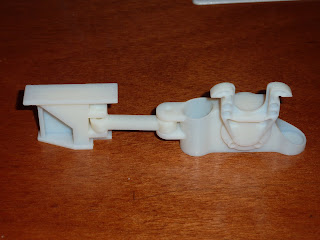
Here are some of the suspension parts 3d printed ready to make silicone moulds from. These have been scaled up to allow for metal shrinkage in the casting process. I had these printed by 3dprintuk and I think they have come out very well. Turn around time was only a few days once the files were finalised. The only hitch came when the post office lost them. Still they found them in the end and the parts turned up ok a couple of days later. These were printed on an Objet machine using a printable photo polymer process. This in my opinion gives much better resolution and surface quality than some of the other technologies in common use.
Here are some of the suspension parts 3d printed ready to make silicone moulds from. These have been scaled up to allow for metal shrinkage in the casting process. I had these printed by 3dprintuk and I think they have come out very well. Turn around time was only a few days once the files were finalised. The only hitch came when the post office lost them. Still they found them in the end and the parts turned up ok a couple of days later. These were printed on an Objet machine using a printable photo polymer process. This in my opinion gives much better resolution and surface quality than some of the other technologies in common use.
Gearbox for 5" wheelset
This shows the general arrangement of the gearbox. This uses ball and needle roller bearings throughout with the gears being keyed to shafts where necessary. The intent is that the grars will be all steel and the whole thing will be grease packed for life.
The ratio used is 8:1 giving around 10mph max speed. It could be geared lower but the motor doesnt need it.
5" Gauge wheelset
This is the arrangement for the wheel set. I'm quite please with it at this stage, I just need to make one up now to test.
As these can go under any external frame 5" bogie, I can test them on one of my other locos.
I have been working away on various bits of the design for the Class 70, mainly on the Bogie design.
I have decided to custom make the wheel sets for this as I like the idea of plenty of power combined with a fully enclosed gearbox. That means a modified motor and complete fabrication of the gearbox assembly.
This is what I have to date. The funny breaks are where the various sections on the bogie frame will be welded together. I intend to use a fair bit of lost wax casting on this project, hence casting in the weld prep where I want it.
Interestingly from my calculations so far, although this is drawn as a 3 motor set up, the 3rd motor adds no real benefit. If 2 motors can produce more power than can be put down onto the track then adding a 3rd actually reduces the tractive effort available to pull away. I have drawn it as a 3 motor setup mainly to confirm that if needed, a 3rd motor can be added. As it stands, the centre axle will probably be free wheeling and very lightly sprung so that the weight falls on the power producing axles at the end of the bogie.
Subscribe to:
Comments (Atom)


